We at,
Prolific Engineers, are
manufacturers, exporters and suppliers of adhesion testers, adhesive testing
equipment, automobile accessories testing equipment, building hardware
testing equipment, cables & conduits testing equipment in India.
Conical Mendral Bend Tester
Determination of elongation of attached
organic coatings such as paints is carried out by the use of a conical
mandrel apparatus. The coating is done on a substrate of mild steel sheet
and rolled over a conical mandrel of specified dimensions. The substrate
gets folded over the mandrel so that a known extension is produced on its
outer surface.
The coating, which is adhering to the substrate, also undergoes extension.
Because of this extension, the coating layer is split into two near the
narrower end of the conical mandrel. The distance of the starting of this
parting from the conical edge when compared with the graphs provided gives
the value of the extension at the point where the parting starts, thus
giving an indication of the extensibility of the coating.
The PROLIFIC Conical Mandrel Bend Tester for paints consists of a conical
mandrel of specified dimensions rigidly held in two supporting brackets. The
substrate with the test coating is held rigidly along one of the tapered
edges of the mandrel. A roller bar, which moves at a set distance from the
outer edge of the conical mandrel, folds the test panel over the mandrel.
The coating is observed with naked eye after folding and the distance of
the beginning of parting from the narrow side of the mandrel is determined.
This distance, when correlated with the thickness of coating, gives its
extensibility.
The apparatus is finished in grey hammertone stoving painting and bright
chromium / zinc plating to give it a corrosion resistant finish.
|
TECHNICAL DATA |
|
Dimensions of conical mandrel |
Major diameter - 38 mm
Minor diameter - 3 mm
Length - 203 mm |
|
Dimensions of pressing roller |
Diameter - 12 mm
Length - 200 mm |
|
Angle of bending |
135° |
|
RELATED STANDARDS |
|
ASTM D 522 - 1985 |
Standard Test Method for Elongation of Attached
Organic Coatings with Conical Mandrel Apparatus |
|
BS 3900 (Part E 11) - 1985 |
Methods for Tests for Paints
Part E 11 : Bend Test (Conical Mandrel) |
|
ISO 6860 - 1984 |
Paints and Varnish - Bend Test (Conical Mandrel)
|
Bursting Strengths Tester
Bursting strength of any material such
as fabric, leather, paper etc. is its strength under multi-directional force
and is defined as the hydrostatic pressure required to produce rapture of
the material when pressure is applied at a controlled increasing rate
through a rubber diaphragm.
The PROLIFIC Bursting Strength Tester is designed to find bursting strength
of fabric / leather / paper / paperboard. A test specimen is held between
two annular clamps under sufficient pressure to minimize slippage. The upper
clamping surface has a continuous spiral groove and the lower clamping
surface has a number of concentric grooves. A circular diaphragm of pure gum
rubber is clamped between the lower clamping plate and a pressure cylinder
so that before the diaphragm is stretched by pressure underneath it the
centre of its upper surface is below the plane of the clamping surface.
The equipment is fitted with a motor driven cam mechanism, which increases
fluid displacement on the lower side of the diaphragm at a specified rate.
The equipment is provided with an arrangement that automatically brings down
the pressure and stops the motor on completion of the test cycle. A digital
pressure gauge with peak memory indicates the maximum pressure attained
before failure of the test specimen.
The equipment is ruggedly designed to give a long and trouble free life.
The components are either chrome / zinc plated or finished in grey
hammertone stoving painting to give the equipment a corrosion resistant
finish.
|
TECHNICAL DATA |
|
Opening in upper clamp |
30.5 mm diameter |
|
Opening in lower clamp |
33.1 mm diameter |
|
Rate of fluid displacement |
95 cm³/minute |
|
Pressure gauges range |
40 kgf/cm² x 0.01 kgf/cm² |
|
Test fluid |
Glycerin |
|
Motor |
¼ HP single-phase 230-volts AC |
|
RELATED SPECIFICATIONS |
|
IS 1060 (Part 1) - 1966 |
Methods of Sampling and Test for Paper and Allied
Products |
|
IS 1966 - 1975 |
Method for Determination of Bursting Strength and
Bursting Distension of Fabrics - Diaphragm Method |
|
ASTM D 774 - 1967 |
Standard Test Method for Bursting Strength of
Paper |
|
ISO 2758 |
Bursting Strength of Paper |
|
TAPPI T 403 - 1991 |
Bursting Strength of Paper |
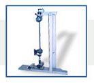
The tearing strength of fabrics, papers,
plastic films, or other similar materials in sheet form is determined by
measurement of work done in tearing through a fixed length of the test
specimen using the Elmendorf Tearing Tester.
The PROLIFIC Elmendorf Tearing Tester consists of a brass sector pendulum
pivoted on anti friction ball bearings over a vertical bracket fixed on a
rigid metallic base. The test specimen is held between two clamps, one of
which is mounted on the pendulum and the other is mounted on the vertical
bracket. The clamps are mounted in such a manner that their holding faces
are aligned with each other when the pendulum is locked in its raised
position.
The pendulum is released by lifting a release lever. This action causes the
pendulum to fall down under its weight and to tear the test specimen while
doing so. The energy absorbed during tearing is indicated on a scale fitted
on the pendulum by a low friction pointer pivoted on the axis of the
pendulum.
An adjustable knife is also mounted on the pendulum support bracket. It is
centered between the two clamps and is used for making the initial slit in
the test specimen.
Check weights are supplied with the tester for verification of the scale.
The apparatus is finished in grey hammertone stoving painting and bright
chrome plating to give it a corrosion resistant finish.
Augmenting weights for increasing the range of the tester for testing high
strength materials are available as optional accessories. Low strength test
specimens may be tested by mounting multiple test specimens at the same
time.
|
TECHNICAL DATA |
|
Capacity |
1600 g (can be increased to 3200 and 6400 g by
adding augmenting weights) |
|
Clamping surfaces of each clamp |
36 mm wide x 16 mm high |
|
Distance between clamps |
2.8 mm |
|
Tearing distance |
43 mm |
|
Scale reading |
0 - 100% of range |
|
RELATED STANDARDS |
|
IS 1060 (Part 1) - 1966 |
Methods of Sampling and Test for Paper and Allied
Products |
|
IS 1397 - 1990 |
Craft Paper - Specification |
|
IS 6489 - 1971 |
Method for Determination of Tear Strength of Woven
Textile Fabrics by Elmendorf Tester |
|
ASTM D 689 - 1006 |
Standard Test Method for Internal Tearing
Resistance of Paper |
|
ASTM D 1424 - 1996 |
Standard Test Method for Tearing Strength of
Fabrics by Falling Pendulum (Elmendorf) Apparatus |
|
ASTM D 1922 - 1994 |
Standard Test Method for Propagation Tear
Resistance of Plastic Film and Thin Sheeting by Pendulum Method |
|
TAPPI T 414 - 1988 |
Internal Tearing Resistance of Paper
(Elmendorf-type Method) |
Co-efficient of Friction Tester
The coefficient of friction is the ratio
of the frictional force and normal pressure acting on two surfaces in
contact with each other. Thus coefficient of friction is an inverse measure
of the relative ease with which a material will slide over a similar or
different material.
The PROLIFIC Coefficient of Friction Tester for plastic films is designed
to find static and dynamic coefficients of friction between two flat
surfaces of flexible plastic films. It consists of a rigid and smooth
horizontal glass platform and an arrangement to measure frictional force
between the test specimen mounted on it and a movable sled.
The horizontal platform is fixed on the base plate and the specimen is held
over its surface with the help of pressure sensitive adhesive tapes. The
other portion of the specimen is held on a metal sled having its bottom face
lined with rubber foam.
The sled is kept over the specimen held on the platform and is made to move
over the platform at the specified speech with the help of a screw mechanism
driven by a synchroset electric motor. It is also connected to a load cell
for measurement of frictional force acting on it. A digital display with
peak force indicating arrangement enables measurement of both the
instantaneous force and maximum force exerted during the slipping operation.
Micro switches are provided to automatically stop the motion at the extreme
ends of the travel of the sled.
The equipment is built on a rigid fabricated steel frame and is finished in
grey hammertone stoving painting and bright chrome / zinc plating to give it
a corrosion resistant finish.
|
TECHNICAL DATA |
|
Range of force measurement |
0 - 1000 g x 1 g |
|
Dimensions of mounting platform |
300 x 150 mm |
|
Dimensions of sled base |
63.5 x 63.5 mm |
|
Total weight of sled |
200 g |
|
Speed of movement of sled |
150 mm/minute |
|
Motor |
Synchroset electric motor |
|
RELATED STANDARDS |
|
ASTM D 1894 - 1967 |
Standard Test Methods for Static and Dynamic
Coefficients of Friction of Plastic Films and Sheetings |
|
ISO 8295 - 1995 |
Plastics - Film and Sheeting - Determination of
the Coefficients of Friction |
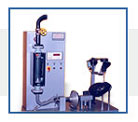
Oxygen index is defined as minimum
concentration of oxygen, expressed as volume percent, in a mixture of oxygen
and nitrogen that will just support flaming combustion of plastic materials
under equilibrium condition of candle like burning. The equilibrium is
established by the relation between the heat lost to the surroundings as
measured by either time of burning or length of specimen burned. This point
is approached from both sides of the critical oxygen concentration in order
to establish the oxygen index.
The PROLIFIC Oxygen Index Apparatus consists of a test column made of
borosilicate glass supported on a brass base. The mixture of nitrogen and
oxygen is released from the bottom of tube, which is filled with glass beads
for mixing and evenly distributing the gas mixture. A specimen holder is
provided to hold the specimen vertically in the center of the test column
with its lower end more than 100 mm above the top of glass beads.
The specimen holder is supported in a glass tube fixed at the center of the
test column and can be taken out and inserted from the column. A
thermocouple probe is also fitted in the test column above the surface of
the beads to measure the temperature of the gases inside the column, which
is indicated on a digital temperature indicator. A tube with suitable
orifice for pilot flame is provided for igniting the specimen by inserting
it from the top of the test column.
Two rotameters with needle valves are provided to control and measure
oxygen and nitrogen flow in the test column. The rotameters are calibrated
with an accuracy of 3% of full-scale range. A timer for indicating the time
of burning with a switch to start it manually is also provided. The
rotameters, temperature indicator, and timer are fitted on a sheet metal
panel on top of which the test column is fixed.
Oxygen, nitrogen and propane / LPG gas cylinder are not provided with the
equipment and have to be arranged by the purchaser.
|
TECHNICAL DATA |
|
Dimensions of test column |
75 mm inside diameter x 450 mm long |
|
Rotameters |
0.625 to 6.25 litre/minute for oxygen
1.05 to 10.5 litre/minute for nitrogen |
|
Temperature indicator |
Up to 199°C x 1°C |
|
Timer |
Up to 999 seconds x 1 second |
|
RELATED STANDARD |
|
ASTM D 2863 - 1997 |
Measuring the Minimum Oxygen Concentration to
Support the Candle- like Combustion of Plastics (Oxygen Index) |
|
BS 5734 (Part 1) - 1979 |
Polyester Moulding Compounds for Electrical and
other Purposes Part 1 : Methods of Test |
The ability of rubber products to
withstand repeated flexing without developing cracks is of prime importance
where such products are used in conditions undergoing repeated flexing.
Flexing endurance of rubber products is determined by simulating in the
laboratory the action of flexing repeatedly under standard conditions of
speed, mode, and degree of flexing.
One of the accepted procedures for determination of flexing resistance
makes use of a De Mattia flexing tester. This tester provides useful
information about the resistance of compounds of vulcanized rubber to flex
cracking when subjected to flexing. Cracks develop in that part of the
surface where stresses are set up during flexing, or if that part of the
surface initially contains a crack, cause this crack to extend in a
direction perpendicular to the stress.
The PROLIFIC De Mattia Flex Tester consists of a set of grips to hold test
specimens in two tiers with their holding faces lying in the same vertical
plane. The flexing and unflexing action is provided by holding one end of
the test specimens in a fixed grip and the other end in a reciprocating
grip.
The set of grips has two fixed grips and one large reciprocating grip
positioned between them in order to flex half of the test specimens while
the other half are being unflexed. The reciprocating grip is fitted with
gunmetal bushes, which slide on hardened and ground rods made of high carbon
steel. The reciprocating motion is provided by an eccentric and linkage
mechanism driven by an electric motor through a V-belt and pulleys.
A six digit electronic counter with reset and memory backup is provided for
indicating the number of test cycles undergone.
The equipment is built on a rigid metallic base plate and finished in grey
hammertone stoving painting and bright chrome / zinc plating to give it a
corrosion resistant finish.
The standard model of the tester is designed to test up to six test
specimens at one time. A special model capable of testing up to twelve test
specimens at a time can also be offered against specific enquiries.
Moulding dies for preparing test specimen and jig and punch assembly for
making initial crack in test specimens for crack growth test are available
as optional accessories.
A special model of the tester, which can test up to twelve rubber specimens
at elevated temperature, is also available. In this model the grips of the
tester are placed inside a double walled oven having a front door fitted
with toughened glass. The inner walls of the oven are made of aluminium
sheet while the outer ones are of CRCA mild steel sheet. The space between
the walls is filled with mineral wool for insulation. An electric heating
element is provided for heating the air in the oven. An air-circulating fan
for uniform temperature distribution in the oven is also provided. The
temperature of the oven is controlled and indicated by a digital temperature
controller cum indicator.
|
TECHNICAL DATA |
|
Number of test specimens tested |
Six or twelve |
|
Maximum opening between grips |
75 mm (adjustable) |
|
Travel of reciprocating grip |
57.15 ± 0.1 mm (adjustable) |
|
Flexing frequency |
300 ± 10 cpm (adjustable) |
|
Motor |
¼ HP single-phase 230 volts AC |
|
Counter |
Six digit electronic counter with memory back up
|
|
RELATED STANDARD |
|
IS 3400 (Part 7) - 1967 |
Methods of Test for Vulcanized Rubber
Part 7 : Resistance to Flex Cracking |
|
IS 3400 (Part 8) - 1983 |
Methods of Test for Vulcanized Rubber
Part 8 : Resistance to Crack Growth |
|
BS 903 (Part A10) - 1984 |
Methods of Testing Vulcanized Rubber
Part A10 : Determination of Flex Cracking (De Mattia) |
|
BS 903 (Part A11) - 1985 |
Methods of Testing Vulcanized Rubber
Part A11 : Determination of Crack Growth (De Mattia) |
|
ISO R 132 - 1983 |
Rubber, Vulcanized - Determination of Flex
Cracking - De Mattia |
|
ISO R 133 - 1983 |
Rubber, Vulcanized - Determination of Crack Growth
- De Mattia |
The Scott flex tester is used for
determination of operational life of flat transmission belts. Five test
specimens taken from the sample of belt under test are flexed repeatedly
over cylindrical hubs under a specified tension. The average number of
flexing cycles which cause the plies of all the five test specimens to
separate gives a measure of its dynamic fatigue life.
The PROLIFIC Scott Flex Tester consists of a set of five test stations,
each station having an arrangement to hold one test specimen of specified
dimensions in a set of self-tightening roller type grips, a hub over which
the test specimen can be bent through the specified angle, and an
arrangement to move the test specimen in a reciprocating motion over the
hub.
The hubs are pivoted on two grease-sealed ball bearings, which are in turn
supported at one end of loading levers. The other end of the loading levers
carry dead weights to apply the required tension on the test specimens in
contact with the hubs. If desired, the position of the dead weights can be
changed to alter the tension on the test specimens. The loading lever can be
lifted by a foot pedal to momentarily remove the tension on the test
specimens for facilitating the observation for ply separation.
The two ends of the test specimens are clamped in a set of self-tightening
grips, which are given reciprocating movement with the help of rocker arms
mounted on a horizontal shaft. An oscillating movement is given to the shaft
through an electric motor and a worm reduction gearbox with the help of an
eccentric and link mechanism.
Individual digital counters with non-volatile memory are connected to each
test station to count the total number of test cycles undergone by each test
specimen. The counter corresponding to a particular test specimen stops
counting when the load is removed momentarily when observing for ply
separation and if the sample is removed. The number of test cycles undergone
by the test specimens is retained in the memory of the counters even if the
power to them gets switched off temporarily.
The various components are mounted on a sturdy steel frame, which is
covered from front, sides, and top with CRCA sheet. The testing area has a
full-length clear acrylic hinged lockable cover to enable observation of
test specimens during the test.
The equipment is finished in grey hammertone stoving painting and bright
chrome or zinc plating to give it a corrosion resistant finished. The frame
is painted black while the testing area is painted white for easy detection
of rubber particles torn loose from the test specimens and to facilitate
determination of the end point.
|
TECHNICAL DATA |
|
Dimensions of test specimen |
210 mm x 25.4 mm x 4 ply |
|
Number of test specimens that can be test
simultaneously |
Five |
|
Diameter of hubs |
32 mm |
|
Angle of contact of the belt around hubs |
165° |
|
Travel of belt in one direction |
66.5 mm |
|
Load on each test specimen |
45 kg |
|
Operating frequency |
160 cycles per minute |
|
Motor |
½ HP single-phase 230 volts AC |
|
Counters |
6 digit electronic type with reset and memory
backup |
|
RELEVANT STANDARDS |
|
ASTM D 430 - 1973 |
Standard Test Methods for Rubber Deterioration -
Dynamic Fatigue
Method A : Scott Flexing Machine |
|
IS 6583 - 1972 |
Specification for Train Lighting Belting |
|
IRS E14 - 1970 |
Specification for Train Lighting Belting |
Hardness is one of the most important
properties which determine the suitability of any rubber component for its
intended end use. Incorrect hardness may defeat the basic purpose for which
the component is designed. Thus accurate and reliable determination of
hardness is of extreme importance in rubber field.
Amongst the various means for the determination of rubber hardness the most
important ones are the Durometer and the IRHD Hardness Tester. While the
first uses the principle of indentation of a truncated cone in rubber under
varying loads acting through a spring, the second method uses a fixed dead
load acting on a hemispherical indenting tip. Whereas the first method
suffers from the disadvantage of permanent set getting developed in the
spring and thus affecting its accuracy, the second method, being based on
dead load principle, is free from this problem.
The PROLIFIC IRHD Hardness Tester is a table model equipment suitable for
reference testing of hardness of rubber or similar polymers in the
laboratory. It consists of a plunger rod carrying a hardened hemispherical
tip of the specified diameter at its lower end. The rod is located within a
cylindrical guide and is constrained to move inside it. The base of the
guide acts as the pressure foot surrounding the point of indentation. Under
normal condition the pressure foot extends below the indenting tip, thus
preventing it from getting damaged. An indenting load is positioned over the
plunger rod without directly acting on it.
The test specimen having flat and parallel top and bottom faces is placed
on a horizontal platform located below the indenting tip. The platform can
be raised up by rotating a screwed wheel. This upward movement of the
platform causes the test specimen to come in contact first with the pressure
foot and later with the indenting tip under the specified contact load.
Depth of penetration of the indenting tip into the test specimen is
determined with the help of a dial indicator fitted at the top of the
pressure foot assembly. The contact between the dial indicator and the top
of the plunger rod is made through an electrical arrangement to ensure that
the weight of the stem of the dial indicator does not act on the test
specimen. An electric buzzer is provided to give low intensity vibrations to
the plunger rod to eliminate friction. The dial indicator gives the depth of
indentation in units of 0.01 mm, which can be converted into IRHD hardness
values with the help of a standard table provided with the equipment.
The tester is finished in grey hammertone stoving painting and bright
chrome plating to give it a corrosion resistant finish. Three models of the
tester are available to cover different ranges of hardness.
|
TECHNICAL DATA |
|
STANDARD MODEL |
LOW STANDARD MODEL |
HIGH STANDARD MODEL |
|
Range of hardness |
30 to 85 IRHD |
10 to 35 IRHD |
10 to 35 IRHD |
|
Diameter of indentor tip |
2.50 mm |
5.00 mm |
1.00 mm |
|
Pressure foot |
20 mm OD
6 mm ID |
22 mm OD
10 mm ID |
20 mm OD
6 mm ID |
|
Force on pressure foot |
8.30 N |
8.30 N |
8.30 N |
|
Contact force |
0.30 N |
0.30 N |
0.30 N |
|
Indenting force |
5.40 N |
5.40 N |
5.40 N |
|
Electric supply |
230 volt single-phase AC |
|
RELATED STANDARDS |
|
IS 3400 (Part 2) - 1980 |
Methods of Test for Vulcanized Rubber
Part 2 - Hardness |
|
ISO 48 - 1979 |
Vulcanized Rubbers (30 to 85 IRHD)
Determination of Hardness |
|
ISO 1400 - 1975 |
Vulcanized Rubbers of High Hardness (85 to 100
IRHD)
Determination of Hardness |
|
ISO 1818 - 1975 |
Vulcanized Rubbers of Low Hardness (10 to 35 IRHD)
Determination of Hardness |
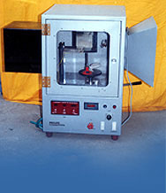
Low Temperature Brittleness
Tester
The brittleness of rubber or other
elastomers at low temperature may be determined with the help of a low
temperature brittleness test.
In this test the test specimens are held at one of their ends in a suitable
grip and a semi-cylindrical edge of a specified radius made to strike them
with a known velocity. The effect of the impact is then examined visually to
evaluate low temperature brittleness of the material under test.
The PROLIFIC Low Temperature Brittleness Tester for elastomers consists of
a test specimen holder to mount ten test specimens at one time, a motorized
pendulum carrying a striking edge which strikes the test specimens held in
the holder, and a double walled cooling bath for cooling the test specimens
in.
The arrangement to mount test specimens can hold up to ten test specimens
at one time. The holder can be rotated to dip the test specimens in the
cooling medium. At the time of impact the test specimens are held in
vertical plane passing through the axis of rotation of the pendulum such
that the striking edge strikes them perpendicular to their face.
The pendulum is pivoted on two ball bearings to give a low friction
movement. It carries at its outside edge a flat metallic bar having a
semi-cylindrical contact edge to strike the test specimens. The pivot axis
of the pendulum is located above the cooling bath. The pendulum rotates at
the desired speed with the help of an electric motor, worm gear, and pulley
set. The speed of rotation of the pendulum is set to give the specified
striking velocity to the striking edge. The motor is started with the help
of a push button and stops automatically with the help of an
electro-magnetic brake after one revolution of the pendulum.
The bath is of double walled construction with inside made from stainless
steel sheet and outside of mild steel CRCA sheet with thermocole insulation
around the outer chamber. The cooling medium is poured in the inner chamber
of the bath from the top and can be removed through a valve at its bottom.
Cooling is carried out by adding powdered dry ice to either the cooling
medium or in the gap between the two chambers. An electric immersion heater
is provided to raise the temperature of the bath. The temperature is
indicated and controlled with the help of a digital temperature indicator
cum controller. A motorizes stirrer is provided to stir the cooling medium
to ensure a uniform temperature in the bath.
The bath and the pendulum are placed inside a sheet metal enclosure having
an acrylic viewing door. The supply to the motor is cut off if the door of
the enclosure is open.
The equipment is finished in grey hammertone stoving painting and bright
chrome / zinc plating to give it a corrosion resistant finish.
|
TECHNICAL DATA |
|
Maximum number of test specimens that can be
tested at a time |
Ten |
|
Radius of rotation of striking edge |
300 mm |
|
Radius of striking edge |
1.57 mm |
|
Speed of rotation of pendulum |
60 ± 3 rpm |
|
Impact velocity |
1.8 to 2.1 m/second |
|
Distance of striking tip from the edge of the grip
|
8.0 ± 0.3 mm |
|
Inner dimensions of cooling bath |
30 x 20 x 14 cm |
|
RELATED STANDARDS |
|
ASTM D 746 - 1974 |
Brittleness Temperature of Plastics and Elastomers
by Impact |
|
ASTM D 2137 - 1983 |
Rubber Property - Brittleness Point of Flexible
Polymers and Coated Fabrics |