We at,
Prolific Engineers, are manufacturers, exporters and suppliers of adhesion testers, adhesive testing equipment, automobile accessories testing equipment, building hardware testing equipment, cables & conduits testing equipment in India.
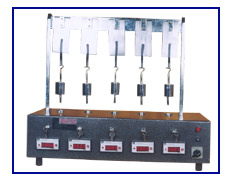
Tape Retentivity Tester
Retentivity of adhesives used in the manufacture of pressure sensitive adhesive tapes under static load is normally determined with the help of a tape retentivity test.
In this test, retentivity of the adhesives tape under test is determined by finding the time taken for removal of a specified length of tape from a polished stainless steel plate under the action of a specified shear-off force applied by mean of a dead weight.
The
PROLIFIC Tape Retentivity Tester consists of an arrangement to test five test specimens at a time, with individual electronic digital time interval meters having memory back-up and controlled by individual micro-switches. Five sets of dead weights, each consisting of one weight each of 1 kg and 2 kg mass, are provided with the equipment for applying the desired shearing force on the test specimens.
Arrangement is provided on the base of the tester to retain the dead weight on failure of the adhesive bond between the test specimens and the polished stainless steel plates. On dropping down, the weight presses a micro-switch to stop the time interval meter corresponding to the test station of the failed test specimen.
The equipment is finished in grey hammertone / black stove enamel painting and bright chrome plating for give it a corrosion resistant finish.
TECHNICAL DATA |
Time interval meters : |
Digital type of 999.9 x 0.1 minutes range with battery back-up to keep recording the time even in case of power failure - five off |
Loading weights : |
1 kg mass - five off
2 kg mass - five off |
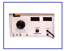
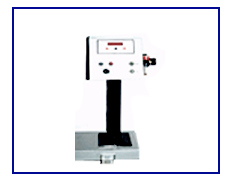
Electric Strength of an Insulating Material is defined as the voltage at which breakdown occurs under the prescribed conditions of test, divided by the distance between the electrodes to which the voltage is applied.
The
PROLIFIC High Voltage Test Apparatus is designed to give an adjustable A. C. high voltage supply. The voltage is provided through an isolated secondary winding of a high voltage transformer. The primary of the transformer is fed a variable voltage through a variac. The voltmeter is directly calibrated to give the output voltage of the high voltage coil at no load.
The high voltage circuit has a tripping system, which automatically trips off the supply, if the current in this circuit exceeds the set value of the tripping current. The tripping current can be set at any desired value within the range of the equipment. A digital mili-ammeter and a digital voltmeter are provided to measure the tripping current and the applied voltage respectively.
A safety device is provided which enables the high voltage supply applied to the probes only on pressing the micro-switch on the probe and only when the actual value of the current is less than the limit of the set tripping current.
The apparatus is housed in a mild steel panel and is provided with one set of high voltage probe and connecting clip.
TECHNICAL DATA |
Input voltage : |
230 V single phase 50 Hz A. C. |
Output voltage : |
0 - 10 kV 50 Hz A. C. |
Tripping current : |
Can be set from 3 to 30 mA |
RELATED STANDARD |
IS 2584 - 1963 : |
Specification for Electric Strength of Solid Insulating Materials at Power Frequencies |
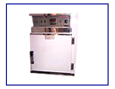
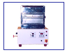
Determination of various physical characteristics of different materials and products at elevated temperatures may be carried out by heating the test specimens to the appropriate temperature inside a constant temperature air oven and determining the required characteristics with the specimens kept under the same temperature. For this purpose the equipment needed for conducting the determination can either be kept inside the oven along with the test specimens, or, if this is not feasible because of certain constrains, by taking the heated specimens out from the oven and conducting the test in still air within the shortest possible span of time.
The PROLIFIC Hot Air Oven (Universal Memmert type) with digital temperature controller has a test chamber of double walled construction. The inner walls are made of aluminium sheet (or stainless Steel) and outer walls of CRCA sheet. The space between the two walls is filled with mineral wool for insulation. The chamber is fitted with three adjustable perforated shelves for keeping the test specimen or the test equipment on.
The oven is heated electrically with the help of heaters placed in ribs on the bottom and sides of the chamber. An air-circulating fan is provided on the back of the chamber for even temperature distribution. The temperature inside the test chamber is indicated and controlled with the help of a digital temperature indicator cum controller.
The chamber is provided with two ports with adjustable openings for enabling natural change of air inside it by convection. These ports can also be used for providing electrical access to the test specimens kept inside the oven, if so desired.
TECHNICAL DATA |
Inner dimensions of test chamber : |
455 mm x 455 mm x 455 mm (or as desired) |
Range of temperature : |
Ambient to 250º C |
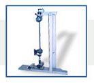
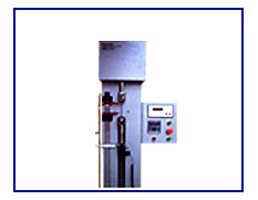
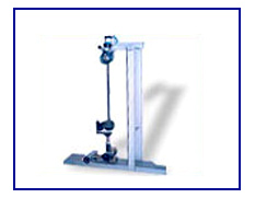
Tensile strength and elongation are the two prime characteristics of most of the raw materials, whether they are metals; or non metals such as rubber, leather, textiles, plastic, paper; or finished products such as rods, wires, ropes, yarns, belts etceteras. These two properties often play a major role in determining the suitability of any raw material for any specified application. It is, therefore, of utmost importance to determine these characteristics accurately, conveniently, and quickly.
The
PROLIFIC Tensile Testing Machines provide a relatively inexpensive way for determining the tensile strength and elongation of a variety of raw materials such as rubber, leather, fabric, plastics, belts, wires, and etcetera. They are based on constant rate of traverse principle, in which one end of the test specimen is held in a stationery grip while the other end is moved at a known fixed speed with the help of a motor, gearbox, and screw arrangement.
The load exerted on the stationary grip is measured by a load cell and is displayed on a digital indicator. The indicator has a peak force retention memory, which can be recalled to display the maximum load exerted on the test specimen before its failure. An overload protection relay is provided to automatically stop the motor if the load exerted goes above the maximum capacity of the load cell.
The movement of the lower grip is indicated on a digital indicator with per-set arrangement to automatically stop the motor at any desired separation of grips.
The speed of traverse of the lower grip is controlled using a frequency based invertor drive and can be changed with the help of six toggle switches to obtain seven traverse speeds. The speed can also be adjusted continuously with the help of a potentiometer. The speed is displayed indirectly as frequency being supplied to the motor by the invertor.
The frame of the test is fabricated from heavy mild steel sections to give it the required rigidity and strength. Various built in safety arrangements such as over-load and over-travel protection, and automatically stopping of the motor on failure of the test specimen are provided.
If desired, the tester can be provided with an arrangement to link it with a computer. Suitable software for calculation of the results and drawing of graph is also provided in such case.
The tester is finished in grey hammertone stoving painting and bright chrome / zinc plating to give it a corrosion resistant finish. The tester is supplied complete with electricals, which include micro-switches, push buttons, and contactors for safe and convenient operation.
A variety of grips suitable for holding different materials or for conducting different tests are available as optional accessories.
Arrangement to plot load versus elongation graphs can be provided against specific requirement.
TECHNICAL DATA |
Capacity of the tester : |
From 5 kg (l.c 0.001 kg) to 5,000 kg (l.c I kg) (the equipment can also be calibrated in other units, such as N, lb etc) |
Speeds of traverse : |
25 mm to 500 mm/min (Other speeds can also be provided) |
Minimum grip separation : |
25 mm |
Maximum grip separation : |
900 mm or 500 mm |
Load measurement : |
With the help of a load cell and a digital display having arrangement to display the maximum load exerted during the test |
Elongation measurement : |
Lower grip movement on digital display (l.c of 0.1 mm) |
Electric controls : |
Push button controls for up and down movement and stopping with help of contactors
Micro-switches for over-travel protection over-load protection
Automatic stopping of motor on failure of test specimen |
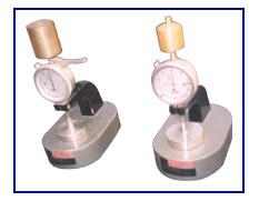
Thickness Gauge (Dead Weight Type)
The thickness of any pressure sensitive material is measured with the help of a dead weight dial type micrometer gauge. Thickness is measured between two circular ground faces, one of which is fixed and the other capable of moving along an axis perpendicular to the faces. The thickness is determined under a specified pressures acting on the sample being measured.
The
PROLIFIC Thickness Gauge (Dead Weight type) is a bench-model instrument. It consists of a rigid cast aluminium base and arm on which a dial indicator is held firmly. The dial indicator has a flat circular pressure foot, which exerts a specified pressure on the specimen kept on an anvil.
The anvil is also circular in shape and has an arrangement to make its upper face parallel to the lower face of the pressure foot. The faces of the pressure foot and the anvil that are in contact with the test specimen are ground flat.
The specified load is applied on the test specimen with the help of dead weight (s) placed on top of the gauge stem.
The apparatus is finished in grey hammertone stoving painting and bright chrome plating to give it a corrosion resistant finish.
TECHNICAL DATA |
| Range of measurement : |
0 - 10 mm (least count 0.01 mm)
Or 0 - 20 mm (least count 0.01 mm)
Or as desired |
| Diameter of pressure foot : |
10 mm (or as desired) |
| Pressure on pressure foot : |
20 KN/m² (or as desired) |
| Diameter of anvil : |
48 mm (or as desired) |
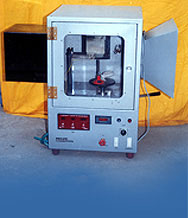
Flammability Tester (Horizontal Burning)
Resistance to propagation of flame of materials used in the interiors of motor vehicles is determined by finding the horizontal burning rate of a test specimen taken from the material under test after application of a standard flame at one end for a specified duration. The test specimen is held horizontally in a U-shaped holder inside a combustion chamber and flame from a Bunsen burner applied at its end. The ratio of the burnt distance and time taken to burn through this distance gives a measure of the flammability.
The
PROLIFIC Horizontal Flammability Chamber consists of a combustion chamber in which the test is conducted, a test specimen holder in which the test specimen is mounted during the test, a standard Bunsen burner to provide the flame, and a set of timers for controlling the flame application time and measuring the flaming time.
The combustion chamber is made form 2 mm thick stainless steel sheet and has a polycarbonate window for observing the test specimen during the test. It has a set of ten vent holes of 19 mm diameter on its bottom and a vent slot of 15 mm width on all the four sides at its top. It is also provided with a channel for sliding in the test specimen holder. The chamber is placed on four 10 mm high legs. A collection pan is provided below the test specimen holder to collect the products of combustion. The pan can be moved from outside of the combustion chamber.
The test specimen holder is made from brass plates. It consists of two parts, the lower part having a slot for exposing the test specimen and pins for holding it. The upper part with corresponding holes presses down the test specimen from top over the holding pins. Lower part is also provided with string of heat resistant wire to support the test specimen.
The test flame is obtained from a standard bunsen burner fixed such that its tip is at a specified location below the test specimen. A needle valve to control the flow of gas to the burner to control the height of flame is also provided.
A pre-set type electronic timer, provided on the equipment, automatically starts as soon as the test specimen is brought in position above the Bunsen burner. It cuts off the gas supply to the burner after the pre-set time (programmable between 0 to 99 seconds) with the help of a solenoid valve. A time interval meter, which can be started and stopped manually, is provided to measure the time taken for the flame to move from the first reference point to the second reference point. Both the timers are fitted on a panel on which the combustion chamber is fixed. The panel is stove enameled to give it aesthetic appearance and long life.
A template made of brass sheet with holes for marking out test specimens of specified dimensions is also supplied with the equipment.
LPG or Butane or Natural Gas cylinder with regulator is not provided with the equipment and is to be provided by the user
TECHNICAL DATA |
Size of test chamber : |
385 x 204 x 360 mm |
Size of lower part of test specimen holder : |
100 x 361 x 10 mm (with `U' shaped opening of dimension 50 x 330 mm) |
Size of upper part of test specimen holder : |
100 x 356 x 10 mm (with `U' shaped opening of dimension 50 x 330 mm) |
Opening of Bunsen burner : |
9.5 mm diameter |
Flame application timer : |
0 - 99 sec (pre-set type) |
Flaming timer : |
0 - 999.9 s |
RELATED SPECIFICATIONS |
IS 15061 - 2002 : |
Automotive Vehicles - Flammability requirement |
ASTM D 5132 - 1993 : |
Standard Test Method for Horizontal Burning Rate of Flexible Cellular and Rubber Materials used in occupant compartments of Motor Vehicles |
SAE - J 369 - Jan 94 : |
Flammability of Polymeric Interior Materials - Horizontal Test Method |
NHTSA - 571 - 302 : |
Flammability of Interior Materials |
ISO 3795 - 1989 (E) : |
Road Vehicles and Tractors and Machinery for Agriculture and Forestry - Determination of Burning Behaviour of Interior Materials |
JIS K 6400 - 1997 : |
Test Methods for Flexible Polyurethane Foam |
SASO 449 - 1988 : |
Motor Vehicles - Flammability of Interior Materials and their Testing Methods |
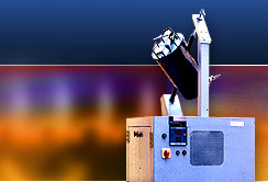
Rearview mirrors used in automobiles shall be able to withstand any impact likely to act on them during their normal life with getting damaged or broken.
Compliance is checked by holding the mirror under test in a suitable frame capable of moving in all three mutually perpendicular directions and a striking it with a rubber lined metal cylinder attached to the outer end of a pendulum free to swing in a vertical plane. The pivot of the pendulum is free to move about two axes so that the pendulum gets deflected from its trajectory plane after striking the mirror.
The PROLIFIC Impact Tester for automobile rearview mirrors consists of a pendulum capable of swinging about two horizontal axes perpendicular to each other. One of the axes is perpendicular to the vertical plane containing the release trajectory of the pendulum. The other axis is at right angle to this axis and serves to move the pendulum away from the vertical plane in which the impact point of the mirror is located. Th-e lower end of the pendulum carries a rubber lined spherical hammer formed by a rigid metal sphere.
The pendulum can be held at the specified angle from the vertical and released from that position with the help of a pneumatic cylinder. The pneumatic system consists of an air filter / regulator / lubricator and a solenoid valve operated by a push button. The angle is indicated on a digital indicator with a least count of 0.1º. The release angle is also adjustable.
An arrangement to arrest the pendulum at the highest angle attained by it after the impact is also provided. The releasing angle and the maximum angle attained after impact are indicated on a digital indicator.
The mirror under test is held on a plate to give it the specified impact. This plate can be moved in up or down, left or right, and front or back directions with the help of a three-directional movement arrangement provided with the tester.
All the components are mounted on a rigid fabricated steel frame. The tester is finished in grey hammertone painting and bright chrome plating to give it a corrosion resistant finish.
Arrangement to provide compressed air to the tester is to be made by the user.
TECHNICAL DATA |
Hammer : |
165 ± 1 mm diameter with a 5 mm thick rubber lining of 50 ± 5 Shore A hardness |
Distance of center of hammer from pivot axis : |
1,000 ± 5 mm |
Mass of pendulum at center of hammer : |
6.80 ± 0.05 kg |
Angle of release of pendulum : |
60° - Adjustable |
RELATED SPECIFICATIONS |
IS 14210 - 1994 : |
Automobile Vehicles - Rear View Mirrors |
JIS D 5705 : |
Mirrors for Automobiles |
InterEurope ECE Regulation No. 0.08.39 : |
Rear View Mirrors Clause 8.2: Impact Test |
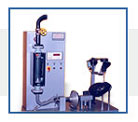
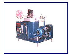
Endurance Tester for Exhaust Seal
The PROLIFIC Endurance Test Rig for Durability Test of Exhaust Gasket (Seal) consists of a stainless steel pipe on which the seal under test shall be held rigidly, another steel pipe with a flange for holding the seal on the first pipe through a spring loaded flexible coupling, and a mechanical arrangement to oscillate the second pipe to an angle of ± 3º (adjustable to ±4º, ±5º or ±6º, if desired) about a horizontal axis passing through the centre of curvature of the outer surface of the seal. The frequency of oscillation is 8 Hz (480 cpm). The oscillating mechanism is complete with an electric motor & gear box and eccentric mechanism for the desired oscillation.
The equipment has a provision for passing hot air through the pipe on which the seal under test is mounted. The air is provided by a blower fitted on the equipment and heated through burning a mixture of LPG gas and oxygen gas. [The LPG gas cylinder and oxygen gas cylinder are provided by the purchaser.] Rotameters are fitted on the equipment to measure and manually control flow of oxygen and LPG gas to control temperature of the seal as indicated on the temperature indicator provided on the equipment. The number of oscillation is recorded on a pre-set type of counter with two pre-set relays. One pre-set relay would cut off supply of LPG gas and oxygen gas by solenoid valves and start a cooling fan to cool the exhaust seal under test after a pre-set value of oscillations and the second pre-set relay would stop oscillation after the second pre-set value of oscillations.
The equipment is finished in stoving hammertone paint and bright chrome/ zinc plating to give it a corrosion resistant finish.
TECHNICAL DATA |
Angle of Oscillation |
Adjustable to ± 3º, ± 4º, ± 5º and ± 6º |
Frequency of Oscillation |
8 Hz (480 cpm) |
Temperature |
Upto 500º C |
Counter |
Six Digit Pre-set type electronic counter with two pre-set relays |
Motor |
¼ HP 220 Volt AC |